Medium
Process:
I've been wanting to get a DRO for my metal lathe for almost a year because it makes finding and re-finding certain positions a lot easier but even the cheapest ones are almost $500 bucks so I made a secret deal with my wife and was fortunate enough to be able to satisfy my wife's requirements of the deal and ordered a DRO on ebay.
The discussions online all vary between getting a cheap-o chinese glass scale DRO or an easy to cut and smaller magnetic scale or to fork out a grand or two and get a really high quality DRO. Considering all my option, I decided to go with the cheap-o chinese glass scales because I don't use my lathe for 40 hours a week and I don't mind going a bit slower and double check my work a bit more frequently than to spend a lot of money on a fancy set of DRO scales.
I bought the following set off ebay: 3 AXIS DIGITAL DISPLAY READOUT DRO FOR MILL LATHE MACHINE AND 3 LINEAR SCALE and have to say that I am very happy with it so far. The manual is crap, but it got me far enough to figure out how to use it.
Once I got the DRO in the mail, I unpacked it and made sure it all worked properly. Then came the fairly lengthy part of installing the scales. For the x-axis I had to actually make a wood patern, use my Aluminum Home Foundry along with the Propane Burner to cast the part, then use the lathe to finish the part.
Installing the y-axis was also a little tricky because I didn't have a lot of space beside the cross slide to mount the scale. I was debating installing it on the left hand side but that would have taken away from the "over the cross slide" capability of my lathe and I didn't want the scale to be too close to the rotating chuck for fear of accidentally damaging it.
The y-axis was probably the easiest but I did require a custom cast ring around my round mill head column so I could mount the scale in a way that would allow it to rotate out of the way when I wasn't using the mill head.
All in all it was a fun project that wasn't too hard and all the custom parts could have been made out of bought stock aluminum so a home foundry wasn't even necessary but it did help keep the cost down.
Update:
Someone inquired about the dimensions of the glass scales I ordered so I thought I'd include them in my post. They are as follows:
Someone inquired about the dimensions of the glass scales I ordered so I thought I'd include them in my post. They are as follows:
X: 31"
Y: 12.5"
Z: 20"
Videos:
Pictures:
 |
| The picture of the DRO from ebay |
 |
| The picture of the glass scale and reader from ebay |
 |
| Another picture from ebay |
 |
| And another one |
 |
| The custom bracket drawn up in FreeCAD |
 |
| The parcel arrived! |
 |
| Unpacking the DRO |
 |
| What a beautiful sight |
 |
| Tapping the first hole into my lathe to install the x-axis scale |
 |
| A view of the lathe with the x-axis |
 |
| Testing the x-axis for levelness |
 |
| Testing various scenarios on how to mount the reader to the carriage |
 |
| The DRO display |
 |
| A custom bracket I bent up to test, but it was too flimsy so I had to go the heavy-duty cast aluminum route |
 |
| Tilting the lathe so I could get to the underside |
 |
| The dimensions of the custom bracket to mount the x-axis reader to the carriage |
 |
| The dimensions, 3D diagram and mold pattern |
 |
| My son adding some lego to my aluminum cast |
 |
| And a toy from McDonalds |
 |
| A 17 pound ingot of aluminum I bought at an auction is now getting melted up. The crystalized grain structure is fascinatingly beautiful |
 |
| A little piece of aluminum I broke off the ingot |
 |
| Another view |
 |
| Machining the custom x-axis bracket |
 |
| Another view of the custom x-axis bracket |
 |
| Holding the x-axis bracket in place for testing |
 |
| Tapping the custom bracket for the x-axis |
 |
| Tapping the carriage apron |
 |
| Milling the recesses for the cap screw heads |
 |
| The installed custom bracket with the angle bracket holding the reader head |
 |
| Side view of the custom bracket |
 |
| View of the installed custom x-axis bracket from underneath |
 |
| The x-axis glass scale done |
 |
| Fitting the reader head cable into a fairly rigid "flexible" electrical conduit |
 |
| The DRO x-axis cable management installed |
 |
| I screwed the end of the electrical conduit into the lathe stand so it wouldn't get caught while working the carriage back and forth |
 |
| View from the end of the lathe |
 |
| Close-up of the installed cable management for the DRO x-axis |
 |
| Getting ready to install |
 |
| Drilling the cross slide for the rear bracket to hold the DRO y-axis |
 |
| The other side of the cross slide |
 |
| Cutting up another custom bracket to hold the DRO y-axis reader head |
 |
| Drilling and tapping yet another hole into the carriage |
 |
| The installed bracket to hold the DRO y-axis reader head |
 |
| Testing the DRO y-axis glass scale for levelness |
 |
| The rough cast of the round bracket for the DRO z-axis |
 |
| Machining it down to size |
 |
| The finished bottom bracket for the z-axis |
 |
| Another view |
 |
| Measuring the center of the bottom bracket |
 |
| Machining off one side to be able to attach the DRO z-axis glass scale |
 |
| Getting ready to mill a gap to read the mill head angle indicator |
 |
| One angle done |
 |
| Another view from a little further away |
 |
| The second angle done |
 |
| The finished bottom bracket for the DRO z-axis glass scale |
 |
| Machining an extension for the bottom bracket |
 |
| Bolting the extension to the z-axis bottom bracket |
 |
| The finished bottom bracket |
 |
| Another view |
 |
| The bottom bracket installed on the mill column |
 |
| The view port that shows the angle indicator marks on the mill column |
 |
| I ended up having to mill the extension down a bit more |
 |
| Milling a slot into the top bracket of the DRO z-axis |
 |
| Testing for levelness of the DRO z-axis |
 |
| The installed z-axis |
 |
| Close-up of the top bracket |
 |
| Close-up of the bottom bracket |
 |
| Another view of the top bracket |
 |
| Cutting the slots into the bracket holding the z-axis reader |
 |
| The finished bracket |
 |
| Tapping holes to hold the bracket to the mill head |
 |
| The z-axis installed |
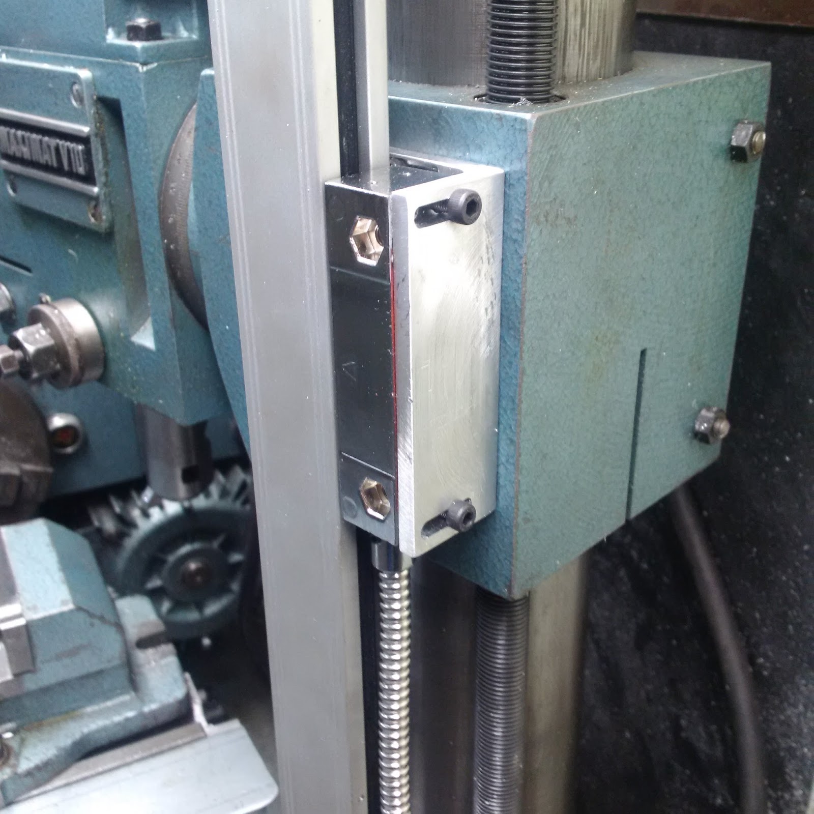 |
| Close-up of the bracket holding the reader head |
 |
| Another view |
Metal band saw
Drill & drill bits
Tap & die set
Hammer
Measuring tape
Ear & eye protection
Metal lathe & accessories
Materials:
DRO kit
12" of 3" x 3" x 1/4" aluminum angle
Cost:
$500.00
Time:
25 hrs
Conclusion:
I love it. It makes working on the lathe so much easier

12 comments:
As usual ... WOW! Great work!!
Hi Chris. you do a really nice work. Congrats.
I have the same Lathe since 3 week. Beautiful piece of tool. :)
And I'm interested by a DRO, and I want to know if you are happy with this DRO.
this is my email : francoisgamache@me.com if you want to reply direct. I live in quebec city and I go often in Moncton. I like this town.
Hello Chris. I really like your blogs. Nice to read :) I´m from Austria (where the Emco is coming form ;) and I bought also a Mximat V10. I also wanted to ask you about the quality of your digital read out DRO. Are you still satisfied with it and do you have problems with the sealings because you have mounted the y-axis in the horizontal position. I´m pleased to get a short answer from you (maybe to daniel_mair@gmx.at) And please don´t stop to post your projects. Best regards from Austria
Can you please tell me what length scales you used? Thanks, Dean
These are the dimensions I gave them; I think they cut the scales a little longer but you'd have to check with them:
I have a lathe/mill combination tool. The x-axis for the lathe has 26 inches travel, the cross-slide of the lathe has 6.75 inches travel and the mill head has 14.375 inches of travel.
hope this helps
Thanks for sharing this! Regarding your round column (Z axis) base bracket - I see that the notch for the 'external keyway' on the column only goes part way through the base bracket.
What was you reasoning for that? Allowing the weight of the mill head and column along with the set screw you added to positively secure the bracket? Or am I missing something here?
Studying the other pictures, I see where the 'external keyway' on the round column does not go all the way to the base - mine does for some reason...
I think the column keyway didn't go all the way down to the bottom and I was being particular about cutting out only as much as necessary to keep the strength of the ring as strong as possible, but in hindsight I could have cut it all the way through and saved me some machining time.
Could you tell me the lenght of the linear scales?
@JM These are the dimensions I gave them; I think they cut the scales a little longer but you'd have to check with them:
I have a lathe/mill combination tool. The x-axis for the lathe has 26 inches travel, the cross-slide of the lathe has 6.75 inches travel and the mill head has 14.375 inches of travel.
hope this helps
Thanks a lot!! I just bought a Emco V10-P :-)
@JM: glad I could help. I would HIGHLY recommend going to groups.io and search for "EMCO V10 Lathes" and join that group. I've found it to be an incredible source of information and help for my V10.
Post a Comment