Creating a spindle lock for my metal lathe
Difficulty Level (Easy, Medium, Hard, Insane):
Medium
Process:
The last thing I had to do to finish the Worm And Worm Gear For My Metal Band Saw was to cut a 3/16" key way into my brass gear. In order for me to do that I had to have a reliable way of locking my spindle. Unfortunately, when this lathe was designed in the 70's they did not provide such a mechanism. A few months ago I slapped together a quick and dirty Spindle Lock For My Emco Maximat V10 Metal Lathe. However, although it prevented the spindle from turning, it didn't lock it into one place.
I wanted to come up with a design that would work, was easy to use and didn't look ugly without having to modify the lathe itself too much.
WARNING: If you're a purist, please stop reading this because you will weep and wail at my audacity to drill and tap holes into this beautiful piece of machinery!!!
After cutting down and milling a piece of 1" by 2" by 6" aluminum, I used a fly cutter to cut out a 3" diameter arc, drilled two holes into the piece of aluminum, clamped it to the head stock underneath the cover, then drilled and tapped two holes right into the head stock.
What I didn't do for the first hole (which I should have) was to remove the gear selector rod. I nicked the rod a bit with my drill bit and after I realized it I removed the electrical panel, un-clipped the c-clip, loosened the set screws that held the selector forks and pulled it out.
WARNING! The little o-rings were so brittle and hard that at first I wasn't able to pull out the rod. I started using a through punch and a hammer but right away I thought I'd better check why it wasn't coming out. I'm glad I checked because the brittle o-rings would have locked the selector fork and the hammering would have definitely broken off the little fork so I'm glad I went easy.
I ended up breaking the o-rings with a little dental tool and after they were removed, the gear selector rod pulled right out.
Once I screwed the aluminum piece into the head stock, I took a 4" by 4" of 1/2" hot rolled steel plate, used the fly-cutter to clean it up, measured and aligned it, then drilled and bored it to 30 thou over size. In retrospect, I should have only made it about 5-10 thou larger but I just had to do a little more clamping with my clamping bolt afterwards.
Once the square plate had a big enough hole to go over the spindle, I drilled, tapped and screwed it into the previously installed piece of aluminum, then took it off again and drilled and tapped the hole for the locking bolt.
After turning a piece of cold rolled steel to size, threaded one end and used my Dividing Head to cut a 13mm hex head into it, all I had to do was drill a 15mm hole into the top of the change gear cover, install the locking bolt and I was good to go!
Videos:
Pictures:
 |
| The spindle with my first version of the spindle lock |
 |
| Tracing out the arcs to cut out with the fly cutter |
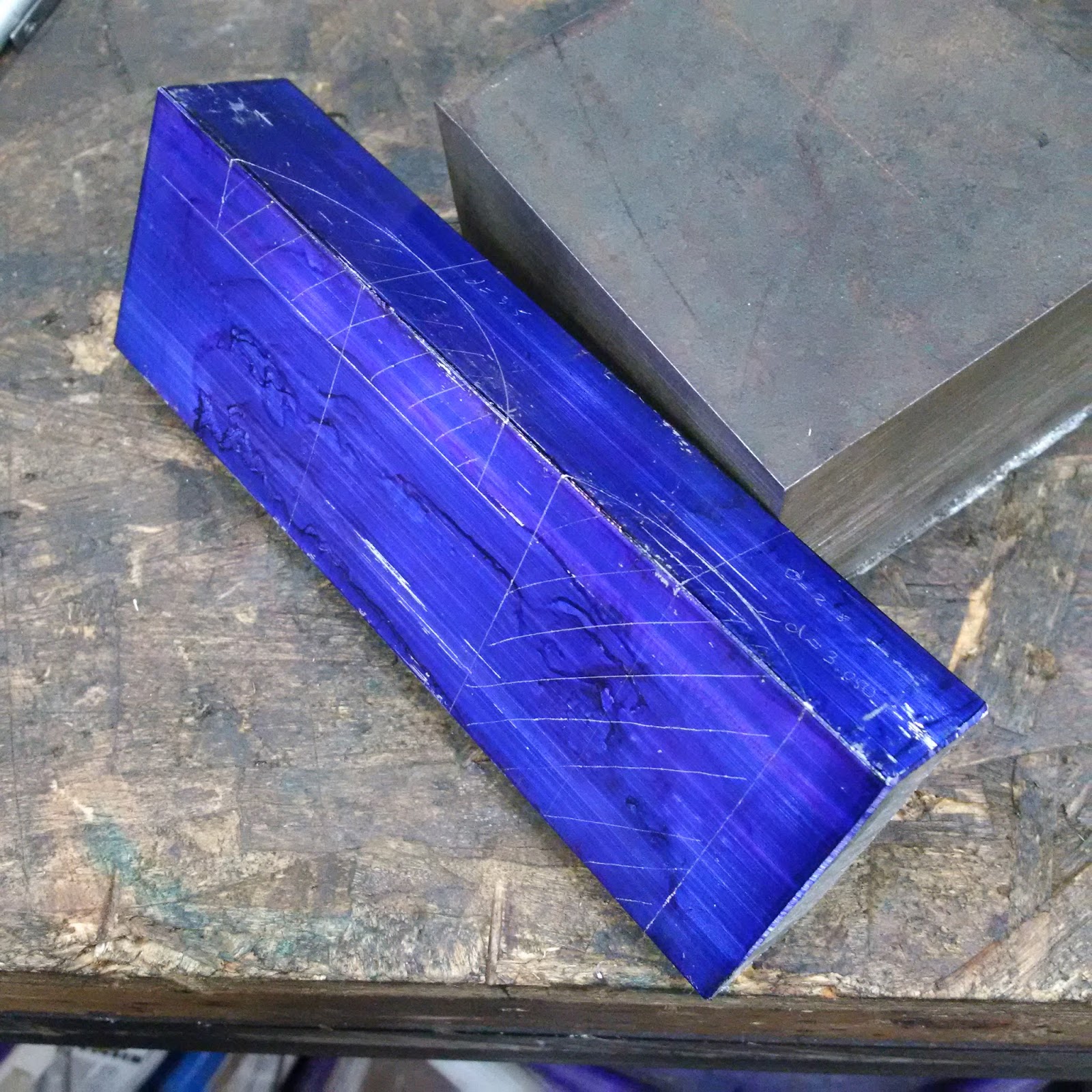 |
| A closer look at the arcs I had to fly-cut out of this piece |
 |
| Setting it up vertically at first but I switched it horizontally later |
 |
| Horizontally mounted the piece so I could use the automatic feed to do the fly cutting |
 |
| The piece after the fly-cutting was done |
 |
| Drilling and tapping the second hole into the head stock |
 |
| Cutting a 4" by 4" piece out of this 1/2" hot rolled steel plate |
 |
| Fly cutting the hot 1/2" plate to clean it up a bit |
 |
| Getting ready to drill and bore the hole where the spindle will go |
 |
| Drilling a 7/8" hole into the 1/2" plate |
 |
| After the piece was drilled, bored and cleaned up |
 |
| Drilling the clamping screw into the locking plate |
 |
| The first bolt installed and testing the locking mechanism |
 |
| Another view |
 |
| The second bolt installed and a 4 thou brass ship at the top of the spindle |
 |
| getting ready to turn the locking bolt down to size |
 |
| After the hex head was cut on the mill with my dividing head |
 |
| The finished locking bolt |
 |
| Another view |
 |
| The installed locking bolt with the cover opened |
 |
| Another view |
 |
| Drilling a hole into the cover |
 |
| The protruding locking bolt |
 |
| Close up of the locking bolt |
 |
| Another view |
Metal lathe & accessories
Tap & die set
Drill press
Angle grinder
Chop saw
Socket wrench set
Metal scribe
Metal square
Dividing head
Angle grinder
Cordless drill
Dental tools
Hammer
Alan keys
Pliers
Clamps
Digital calipers
Materials:
Layout fluid
4 small o-rings
4" of 5/8" cold rolled steel
6" of 2" by 2" aluminum
4" by 4" of 1/2" hot rolled steel plate
4 bolts
Cost:
$10.00
Time:
5-10 hrs
Savings:
Not sure. Probably a couple hundred bucks if I had to pay someone to do it for me
Conclusion:
It works awesome and looks pretty good if I may say so myself

4 comments:
Do you know what the o'ring sizes are for the Maximat V10 spindle shaft end plates and the rear shaft left side?
Kind Regards,
Ernst Conradie
ernst@ringfeder.co.za
Do you know what the o'ring sizes are for the Maximat V10 spindle shaft end plates and the rear shaft left side?
Kind Regards,
Ernst Conradie
ernst@ringfeder.co.za
I know the post is old.. but great job...I was gifted a maximat 7 with milling head last year and loving it.. I'm HOOOKKKEEEDD>>...
Welcome to the club! I would highly suggest joining the emco larger lathes group on the .io domain. Lots of great folks with the same machines.
Post a Comment