Sunday, February 21, 2016

Fixing Carrier 90 Gas Furnace Limit Switch (#13 and #33 Error)

Project:
Fixing the #13 and #33 error on a 90% efficiency carrier furnace with variable speed blower motor

Difficulty Level (Easy, Medium, Hard, Insane):
Easy

Process:
Two nights ago before going to bed I noticed that the house seemed colder than normal so I checked out the thermostat and saw that there was a "System Malfunction" notice. I decided to go down to the furnace room and have a look at it.

I had a slight suspicion as to what the issue could be and just like I expected I saw the #13 error. After consulting the error code section in the manual that came with the furnace it specified a "Limit circuit lockout" error.

The reason I was expecting this error was that two days ago I got the #33 error (Limit circuit fault).

Basically what that means is that one of the thermal cut-off (TCO) switches would trip and throw the #33 error, but this time it seems like the TCO/Limit switch failed and got stuck in the open position.

As it was getting late, I decided to turn off the furnace main switch and see if it would reset over night. Unfortunately, at 6:20am when the house should be warming up it wasn't so I knew I'd have to do some more trouble shooting and then fix the issue.

I hauled out the volt meter and confirmed that the limit switch was in fact showing no continuity and had failed in the open position.

I disconnected the two wires and temporarily by-passed the limit switch and spent the next hour sitting beside the furnace while the house was heating up to a nice temperature. Of course, I couldn't leave the furnace on without the safety feature of the limit switch but with my stay at home wife and three small kids I wanted to make sure the house was at least not cold.

After some more research I concluded that the two most likely causes for the error were:

1. Stuck high-heat gas valve
2. Broken limit switch

I suspected #2 because admittedly, I had not been very diligent in cleaning out my furnace air filter, which I supposed caused a reduced air flow through the heat exchanger and consequently a reduced transfer of heat away from the furnace which resulted in the tripping of the limit switch.

After sourcing a part through one of our local furnace repair shop I loosened the two screws, pulled out the old limit switch, put in the new one and everything was back to normal.

Luckily, it was just a $30 part and since I did my own labor it was a fairly cheap problem. However, if I had to get a furnace specialist to come in, trouble shoot the issue, order the replacement part and come back to install it I would have looked at a bill of at least $300 bucks.

Videos:


Pictures:
Part of the trouble shooting manual showing the #13 and #33 errors
The limit switch
Old limit switch stuck in the open position
Manual override of the limit switch - NOT RECOMMENDED
Limit switch model
Carrier furnace type
The replacement limit switch
Brand new limit switch
Close-up of the limit switch
While I was at it I also cleaned the stainless steel probe
Temperature right by the limit switch. Clearly after cleaning the air filter it was within proper limits

Tools:
Socket set
Screw driver
Pliers
Thermometer
Volt meter
Flashlight

Materials:
1 limit switch

Cost:
$35.00

Time:
1hr

Savings:
$270.00

Conclusion:
House is nice and warm and no more errors
Sunday, February 14, 2016

Fixing My MIG Welder

Project:
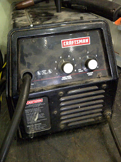
Fixing the wire feed mechanism for my cheap-o Craftsman MIG Welder (Model: 117-076-902)

Difficulty Level (Easy, Medium, Hard, Insane):
Medium

Process:
About 9 months ago I started noticing that my MIG welder wasn't working very well anymore. At first I thought it was something wrong with the mechanism that creates the welding current, but after some investigation I found out that it was actually the motor that feeds the welding wire. After taking it apart, cleaning and re-greasing all the gears and putting some oil in the bearings of the wire feed motor I thought I had fixed it. Unfortunately - and although it did work better for a while - that was not the case.

After some more investigation, I found that the actual issue was not the motor, but the board that controls current TO the motor.

After doing some searching online for a replacement part I was shocked to learn that it was going to be over $100 bucks including the shipping and exchange.

Naturally I went looking for an alternative solution. I discovered that the motor itself uses direct current, up to 30V, depending on how fast I wanted to feed the welding wire. So I thought that I could just use one of my voltage regulators I had bought off ebay a while back.

After the little buck step down converter was installed, I fired up the welder and it worked great! For about 10 seconds and then one of the capacitors on the buck converter blew up.

Back to the drawing board.

In the meantime I used my bench top power supply and hooked it up to the wire feed motor which meant that every time I wanted to weld something I'd have to haul out the power supply, hook it up to the welder and then I was able to do my welding.

Naturally, that wasn't going to be a permanent solution. I measured the voltage input for the old regulator and found that never exceeded 40V so I ordered a more high-rated buck step-down converter from ebay. After a LONG 8 weeks I finally got it, installed it, and wouldn't you know it, after 15 seconds that one blew up too!

So, after some more pondering I remembered that I had taken apart an 18V power transformer from my son's 18V electric bike and thought that if I could hook up that power transformer inside the welder and use the 18V as an input for the step-down converter it should no longer blow up.

I ordered a THIRD AC-DC DC-DC 3A Step Down Regulator I/P 6-36VAC 6-50VDC O/P 3-36VDC from ebay and got it after ANOTHER 8 weeks of waiting. Last night, I finally took some time to install it and surprisingly, it only took a little over an hour to do so now I have a fully functional MIG welder again.

Pictures:
The front of my welder
The side of the welder
Model and S/N info
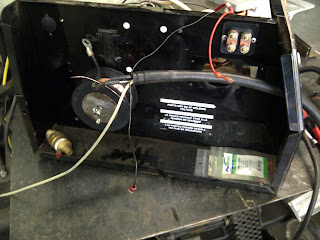
The left side of the welder where the wire feed mechanism is
The wire feed motor and mechanism
The gears for the wire feed mechanism
Another view
The right side of the welder with the coils
Getting ready to install the power transformer and the buck step down converter
Power transformer (right) and step down converter (left)
Close-up of the power transformer
Close-up of the buck converter
The finished beauty
Tools:
Drill
Screwdriver
Pliers

Materials:
Wire
Marretts
Buck step-down converter
18V power tranformer

Cost:
$10.00

Time:
2 hrs

Savings:
$90.00

Conclusion:
Success. I hope it will last.

Making A New Pot Lid Knob

Project:
Making a new knob for one of my mom-in-law's pot lid

Difficulty Level (Easy, Medium, Hard, Insane):
Easy

Process:
The very first "actual" project that I used my lathe for shortly after I got it was replacing a little knob for one of our pot lids. Now, over half a year later I guess word got around that these knobs can be "fixed" so my mother in law brought her broken knob along with the lid it came off of.

This one was actually quite simple. The biggest challenge was to keep the Teflon in the chuck because it's so slippery and it wasn't a very big piece.

All I had to do is take a 2-1/8" hole saw, cut out a slug out of one of a couple of 1" thick pieces of Teflon I bought about 6 months ago for $20 at a scrap yard (which I've used for several small projects since), chuck it up in my lathe and turn it to its final shape.

Then I had to bore the inside out (0.160" deep), drill and tap a hole and clean it up and it was done. Scored some extra points with my mother in law (not that I had to though).

Videos:

 
Pictures:
The broken knob
The lid and knob disassembled
Getting ready to cut out a chunk of 1" Teflon with a 2-1/8" hole saw
The slug after it was cut out
Chucking it up in the lathe
The underside bored to its proper dimensions
Drilling the hole in preparation for tapping it
The finished knob
Another view
Installed on the lid
Another view
And I got me another happy customer
Tools:
Lathe & accessories
Hole saw
Drill
Tap & die set

Materials:
2-1/2" by 2-1/2" by 1" piece of teflon

Cost:
$0.00

Time:
30 minutes

Savings:
$20 bucks maybe?

Conclusion:
It works great and my mother in law is happy

Saturday, February 13, 2016

Bench Top Drill Press

Project:
Refurbishing my 8" Jobmate drill press

Difficulty Level (Easy, Medium, Hard, Insane):
Easy

Process:
I bought this drill press at an auction for $15 bucks last fall and I figured that if I sand blasted it and gave it a nice coat of paint it would probably sell for 50 or 60 bucks. Since it's been standing around in my shop for too many months months, I wanted to get it done. I had the DIY Sand Blasting Cabinet all set up for my Metal Band Saw refurbishing project (blog to come) so it was now or never.

Taking it apart took about 15 minutes, sand blasting took another 30. The vertical column was pretty corroded so after sand blasting it I put it in my lathe and used some emery cloth to shine it up really nice. The painting  only took about 15 minutes and after the paint was all dry, I put it back together and have to say that I am amazed how much of a difference some paint can make. See for yourself.

Pictures:
The rusted drill press the way I bought it
Another view
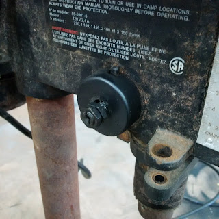
Close-up of the depth stop
After the depth stop was removed
Close up of the rust
Masking off the decals
Masking off the spindle and other sensitive parts
Some of the smaller parts
After sand blasting
Close up of sand blasted parts
Painted base
Painted work table
After it was put together
Another view
Inside the speed change box
Front view
Close-up of the depth stop
Tools:
DIY Sand Blasting Cabinet
Lathe and accessories (for cleaning up the vertical column)
Wrenches
Alan key
Pulley extractor
Screwdriver
Needle nose pliers

Materials:
1/2 can of black gloss metal paint

Cost:
$5.00

Time:
2 hrs

Earnings:
$40.00

Conclusion:
Looks really nice. Maybe I should keep it for myself...

Followers