Saturday, October 17, 2015

Hockey Jersey Display Case

Project:
Building a hockey jersey display case for our former youth pastor

Difficulty Level (Easy, Medium, Hard, Insane):
Medium

Process:
I was asked to build a jersey case for our former church's former youth pastor as a sign of appreciation of all the years of heart and love and time he has invested in this ministry. To me it was a fairly sentimental project because he has grown to be a close friend of mine and I know the passion he has for seeing teens grow in their love for Jesus.

There are many frames out there that are fairly straight forward, pretty simple and would probably do the job for most situations but I wanted this to be something of high value to reflect the quality and love he has invested in these teens.

The first thing I had to do after I got the custom-made jersey is take the measurements, cut and plane down some solid oak for the sides. The trim was too intricate to make so I had to go buy that at Kent but I couldn't believe how expensive that stuff was. It was like $40 for a short 6 foot piece.

After I got the trim I had to cut out a recess so I could mount it on the side frame and another recess for the glass to slide in. Because I wanted to make it removable I had to cut a slot into the top piece where the glass could be taken out in case he ever wanted to change the shirt or if the glass pane broke.

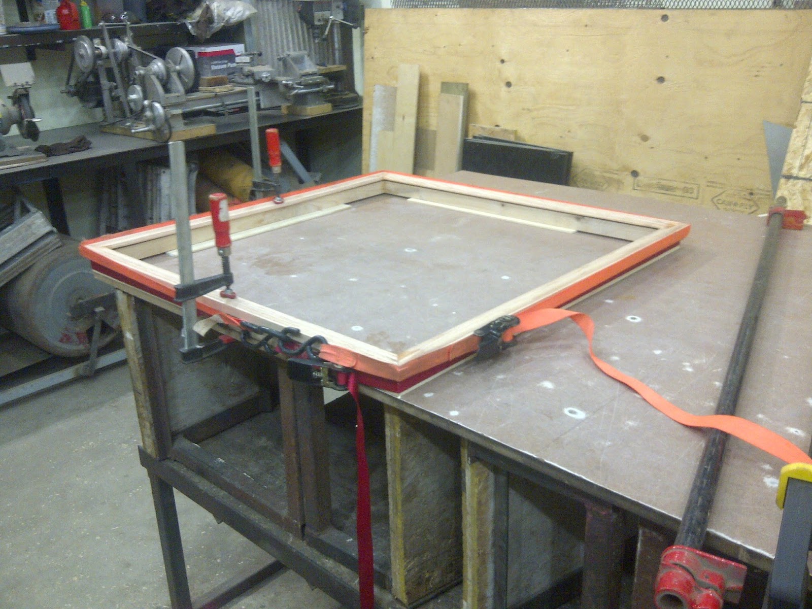
After squaring it up and gluing it all together I did a test fit with the shirt and the glass pane, then gave two nice coats of black paint. The last thing to do was to cut up a piece of wood for the back and one to hang up the shirt inside the case.

Pat, you are an incredible person, have such a passion for these teens and I admire that more than a little jersey frame could ever express!

Pictures:
The shirt folded the way it will sit in the case
The trims
The wood notched and ready to be glued together
Gluing the side and top trim together
Many clamps to evenly glue it together
Cutting the angles on the miter saw
A close-up of the end of the trim
Two of the pieces ready to be glued together
Doing a test fit
Notching out the top trim to allow sliding out the glass pane
Another view of the slot in the top trim
Gluing the frame together
Painting the back
Another view
The frame put together
Cutting the wood to hang the jersey
The finished jersey case
Another view
Another view
Honoring an amazing man
Tools:
Table saw
Chop saw
Hammer
Measuring tape
Pencil
Belt sander
Hand file
Drill
Paint brush
Ratchet straps
Clamps
Planer

Materials:
16' of 1"x2" solid oak
16' of solid oak trim
3' x 3' piece of 1/8" hardboard
Glue
Paint
3' x 3' piece of 1/8" glass

Time:
14hrs

Conclusion:
This was a fun project for an amazing person

Fixing Storm Door

Project:
Fixing the storm door window

Difficulty Level (Easy, Medium, Hard, Insane):
Easy

Process:
I noticed that the window pane of our front storm door had slidden out of the aluminum frame and left a gap of about 1/4". I wasn't too concerned about the gap but the window could possibly shatter if too much pressure was put on it by its diagonal sliding so I figured I'd better fix it.

The process was pretty simple:
  1. take the window frame out of the door
  2. take the window frame apart
  3. slide the plastic trim back over the window
  4. slide that back into the aluminum trim
  5. install the trim back in the window
  6. install the window back in the frame
  7. all done
Pictures:
After the window frame was removed
The split frame
After the window was taken out of the frame
The parts of the storm door
The trims of the storm door
Close-up of the good side
Another close-up
From left: window frame, plastic trim, glass pane
After the plastic trim was put back on the glass pane
After the aluminum trim was put back on the window
Punching the frame to hold to the bracket
Another view
Close-up
After the aluminum trim was punched to hold the brace
Ellie helping me out
The window all put together
The window frame put back together
The finished storm door
Tools:
Swiss army knife
Hammer

Materials:
None

Cost:
$0.00

Time:
1hr

Savings:
$300.00

Conclusion:
Works like a charm

Friday, September 11, 2015

Fixing My Metal Lathe

Project:
Fixing my Emco Maximat V10 metal lathe

Difficulty Level (Easy, Medium, Hard, Insane):
Easy

Process:
A few weeks ago I aquired (or should I say my wife "let" me aquire) a 1973 Emco Maximat V10 metal lathe. I knew there would be some things that required fixing and I had already fixed the Push Buttons For My Emco Maximat V10 Metal Lathe a few weeks earlier but two nights ago I was out in the shop doing some "just for the heck of it" turning (medium speed, cold rolled steel, 10 thou cut on 2 thou per revolution feed speed) and all of a sudden the lathe just stopped. It sounded like power was going to the motor (there was some humming) but the lathe had stopped turning. Of course I turned off the switch right away but I knew there was something wrong.

I started some troubleshooting and was able to turn the chuck by hand with no restriction so I knew it wasn't some locked up gear issue, and while turning the chuck by hand I could see the shaft in the motor housing turning freely so I knew the motor wasn't seized up.

After consulting with my Emco lathe peers at the Emco Lathe Yahoo Group I got a sneaking suspicion that the capacitor might be shot so I did some testing as per the video I found on youtube (link below in the Videos section) I concluded that the old capacitor was in fact deader than dead.

Fortunately, I did have a similar capacitor lying around in my spare electronics bin (I can't even remember where I got that one from, but I must have taken it off an old motor some time ago) so I put that one in and the lathe worked perfectly. The lathe started up full speed and worked as expected, except for the capacitor literally exploded about 5 minutes into my exercise with a big bang and a whole lot of smoke and everything. So I wondered if there was something wrong with the motor that causes the second capacitor to overload as well or if my "new" capacitor just didn't have the right rating. The original capacitor states "anlasskondensator" which translates into "starting capacitor" (I grew up in Switzerland so German was our official language). The only thing I could think of was that the original capacitor was rated at 330V whereas the new one was rated at only 220V. I figured that running on a 125V circuit the 220V would be sufficient, come to find out (and later confirm with my multimeter) that with A/C capacitors the voltage across the two terminals is actually about 1.6 times the rated capacity of the motor, which in my case turned out to be 267V, clearly too much for my "new" 220V capacitor.

After some more research I found out that there actually is a difference between a "Motor Running Capacitor" and a "Motor Start Capacitor" (I linked a great video from youtube that explains it well below in the Videos section). Even though the translation from german would make the "anlasskondensator" a "starting capacitor" it really should be translated as "running capacitor". Who knew?

My conclusion was that either:

1. The first "new" capacitor I used was actually a motor start capacitor instead of a motor run capacitor, or
2. The voltage rating of the first "new" capacitor was under-sized (the original was 330V and the first "new" one only 220V)

In the morning and after some calling around I actually found a local store (Wolsley) that sells parts for HVAC systems. Come to find out that these "RUNNING" capacitors are used all the time for larger motors such as A/C units and even washing machines.

I picked up the new capacitor for $27 bucks and plugged it into the lathe and there it was purring again like a 42 year old kitten. The chips were flying and the old capacitor (manufactured in October 1969) is now laying on my work bench awaiting to be taken apart with my son some other day.

Videos:


Pictures:
The two capacitors in the back of the lathe above the motor (the smaller one is for the milling attachment)
Closeup of the lathe capacitor stating 10/69 as the manufacturing date (!)
No resistance across the terminals indicates dead capacitor
Size comparison with the new capacitor (brown) that I had lying around in my electronics bin
Testing the new capacitor
The new capacitor all tucked away
5 minutes later the smoke was rising from the exploded "not-so-new-anymore" capacitor

After I opened the rear, the smoke was pretty intense
Both (now) blown capacitors
The writing on the two original capacitors. The 20uF capacitor is for the milling attachment
The new properly sized motor running capacitor
Tools:
Screw driver
Knife
Wire stripper
Wire crimper

Materials:
Two 6" pieces of wire
3 wire clamps
1 new capacitor

Cost:
$26.79

Time:
2hrs

Savings:
At least $100 bucks over if I had to call an HVAC guy to come replace the capacitor

Conclusion:
Success. I hope it will last a little longer than the last "new" capacitor

Wednesday, September 9, 2015

Scrap Metal Storage Shelf

Project:
Building a shelf for all my scrap metal pieces

Difficulty Level (Easy, Medium, Hard, Insane):
Easy

Process:
About 5 years ago I bought some 6" sonotubes, cut them to 2ft lengths and tied them together with some ratchet straps to store my scrap metal. However, over the years, the weight of the metal squished the cardboard sonotubes and the shelf started leaning forward. It was getting worse and worse to the point where you would just lightly bump the shelf and the scrap metal would slide out so I knew I'd need to re-visit my scrap metal storage solution.

I liked the concept of using sonotubes because they're fairly cheap but they're not strong enough to hold the weight of all the scrap metal so I figured I could weld a solid shelf out of 3/4" by 3/4" square metal tubes for the strength but then use sonotubes cut in half I could create 35 compartments into which I could organized all the different types of scrap metal to find it easier.

I cut up eighteen 30" pieces, welded them horizontally every 4" to create 7 shelves, cut the sonotubes in half and then to 2ft lengths. All I had to do is slide them into the shelf and put in the metal.

Pictures:
The sides of the shelf
The front of the welded shelf
The new 12' sonotubes to replace the rest
The old, sad looking scrap metal storage
Another view of how it's leaning forward and squished
The old sonotubes that are all squished up
The welded shelf before putting in the sonotubes
After the first row of sonotubes was placed in the shelf
After all the sonotubes were placed in the shelf
The finished shelf in its place
After the scrap metal was sorted, organized and placed in the shelf
A close-up of the sorted scrap metal. From the bottom up:
Solid square, solid round, flat, angle, hollow square, hollow round
Tools:
Table saw
Angle grinder
Belt sander
MIG welder
Clamps
Soap stone pencil
Square
Measuring tape

Materials:
45' of 3/4" x 3/4" square tube (cut into 18-30" pieces)
7' of 1"x1/8" angle iron (cut into 4-20" pieces)
3-6" sonotubes, 12ft long (cut in half and then into 36-2ft pieces)

Cost:
$75.00 ($27 for square tube, $4 for angle iron, $36 for sonotubes)

Time:
3hrs

Savings:
Not sure what this would have cost

Conclusion:
Love it; now I can finally find my stuff!

Followers