Wednesday, January 6, 2016

Threading Insert Tool Holder

Project:
Building a threading insert tool holder / boring bar to allow me to cut internal 1mm metric thread for the Ejector Nut for my Emco Maximat V10 Mill

Difficulty Level (Easy, Medium, Hard, Insane):
Medium

Process:
The process in itself was fairly easy, but because I had never built one of these it took a little fiddling around. Also, I learned that a sharp end mill makes all the difference in cutting O1 tool steel. Duh...

I was getting ready to build the ejector nut for removing the end mill holder of my mill, but had not yet had a need for a small (under 5/8" diameter) internal thread so the first thing I had to do is build a tool holder for one of my threading carbide inserts I had scored on kijij a few months back.

I took some 1/2" O1 tool steel that I had bought at Metals R Us in Dartmouth, NS a while back, cut off a 5" piece and milled a triangle out at the end to hold my insert. After matching up the tilt-angle of the insert with another boring bar, I milled off about 60 thou at the top and about 80 thou at the bottom, then drilled and tapped a hole for the screw that holds down the insert.

After it was all milled to size, I hardened it by heating it with my oxy/acetylene torch to a bright cherry red and quenching it in motor oil. After it had cooled down I sanded the surface to reveal the shiny metal and tempered it to a slight straw color.

After letting it cool down slowly I was ready to re-install the threading insert and cut the internal thread for the ejector nut.

Pictures:
Using some Dykem layout fluid to mark the line to mill
Milling the top flat
Marking the height of the threading insert
The milled, drilled, tapped and installed threading insert
A side view
Top view
Dialing in the shank to mill
The finished threading insert tool holder
Threading the internal 1mm metric thread
The finished ejector nut
Tools:
Lathe and accessories
Angle grinder
Oxy/Acetylene torch
Tap & die set
Metal scribe

Materials:
Dykem layout fluid
6" of 1/2" O1 tool steel
Internal threading insert
Old motor oil

Cost:
$10.00

Time:
3hrs

Savings:
Probably at least $100 bucks if not more

Conclusion:
It worked pretty good. I ended up having to grind off some off the side of the bar but after that it worked great.

Ejector Nut for Emco Maximat V10 Mill

Project:
Building an ejector nut to remove the tool jammed in the mill spindle

Difficulty Level (Easy, Medium, Hard, Insane):
Medium

Process:
In order to cut the worm and worm gear for my Meatal Band Saw repair I had to be able to remove the tool that was jammed in the spindle for my mill and in order to do that, I had to follow another fairly lenghty rabbit trail as follows:

1. I wanted to remove the tool from the mill spindle
2. To do #1, I needed an ejector nut
3. To do #2, I needed to be able to cut an internal 1mm metric thread
4. To do #3, I needed a 39-tooth conversion gear
5. To do #4, I needed to have a fly cutter, a threading insert tool holder as well as a dividing head

After I built the Dividing Head, the 39-tooth conversion gear and the Threading Insert Tool Holder I was able to cut the 1mm internal thread with my Fly Cutter into the ejector nut and use the dividing head again to cut a 13mm hex nut at the other end.

This project was actually quite fun. Once I had all the tools I needed, all I had to do is turn down a piece of mild steel, drill, bore and thread one side and use the dividing head to cut a hex nut on the other end.

Once the ejector nut and the ejector pin were built it was simply a matter of taking a wrench on the ejector nut and an adjustable wrench on the mill holder side and tighten them up to eject the morse taper #2 (MT2) tool which was locked in the mill spindle.

Pictures:
The top of the mill spindle
Hand drawn diagram of ejector nut
AutoCAD diagram of ejector nut
Drilling and boring the ejector nut
Cutting the internal 1mm metric thread with the newly built threading insert tool holder
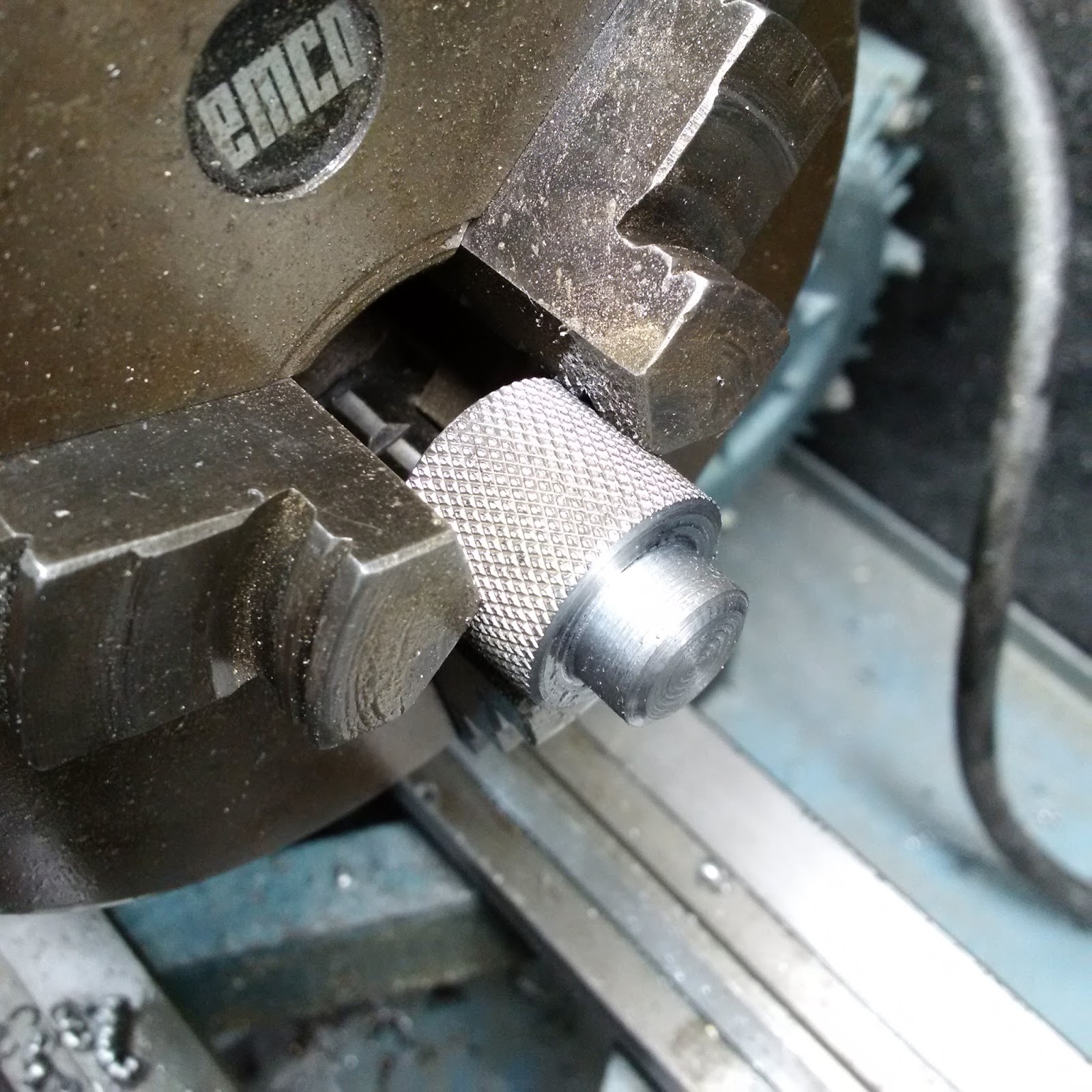
After the outside was knurled and the hex nut side was turned to size
Using the dividing head to cut the hex nut
Close-up of mill before the first cut
Getting ready to cut the second (of six) sides of the hex nut
Getting ready to cut the third side
The finished ejector nut
Another view
The ejector nut installed on top of the mill spindle
Another view
The removed end mill holder
Tools:
Lathe and accessories
Dividing head
Angle grinder
Threading insert tool holder

Materials:
2" of 1.25" cold rolled steel

Cost:
$0.00

Time:
2hrs

Savings:
Probably at least $50 bucks

Conclusion:
I have now finally and successfully removed the MT2 end mill holder from the mill spindle

Diamond Dresser Tool Holder for my Emco Maximat V10 Metal Lathe

Project:
Finding a way to hold a diamond dressing tool to dress the grinding wheels on my Tool Post Grinder

Difficulty Level (Easy, Medium, Hard, Insane):
Medium

Process:
After I built my Tool Post Grinder Holder to true up my 3-jaw chuck I needed a way to dress the grinding stone so I ordered some Diamond Dressing Tools on ebay and got started thinking about how to hold the tool in a way that is completely adjustable in all 3 axes.

After some thinking and researching I decided to create a base out of metal that clamps to the bed ways with a vertical threaded rod (adjustable in the z-axis), then have a horizontal piece of threaded rod which allows the tool to be adjusted in the x and y-axis and a last bushing that would allow turning the tool holder in different angles.

The horizontal piced had to be long enough to reach over the carriage of the lathe and it had to be sturdy enough not to bend when the diamond tip made contact with the grinding stone.

After the bushings were turned down and milled on one side, I brazed them to the threaded rod with some bronze brazing rods. I did this three times and drilled/tapped the final bushing to accept a bolt to tie down the diamond dresser.

In retrospect, I probably could have simplified things a bit and lose some of the adjustability, but since it won't be used all that often it will do just fine.

Also, although I used 5/8" threaded rod, the tool holder is still a bit more flexible than I would have liked it to be.

Pictures:
Drilling the support brackets
The finished diamond dressing tool holder
Another view
Close-up
Tools:
Measuring tape
Marker
Drill press

Materials:
12" of 5/8" threaded rod
2" of 1-1/2" cold rolled steel
3" by 4" by 1/4" mild steel plate
Two 5/8" nuts cut in half
Brazing rod
1 set screw

Cost:
$10.00

Time:
3hrs

Savings:
$50

Conclusion:
I would probably give it a 6 out of 10 because there's a bit more flex in the threaded rod than what I would have liked it to be.

Clamping Set for my Emco Maximat V10 Metal Lathe

Project:
Building a tie-down/clamping set for my metal lathe/mill

Difficulty Level (Easy, Medium, Hard, Insane):
Easy

Process:
When I was working on the Dividing Head, I came to a point where I had to clamp a piece down to the mill table which was too large for my vise so I decided that instead of buying a Step Block and Clamp Set for about $75 bucks (CAD) at Harbor Freight (I might still buy one at some later time) I would make a quick set in my shop.

The bolts were made out of 1045 and hardened/tempered with my oxy/acetylene torch. The clamps were made out of some scrap 3/8" mild steel I had in my Scrap Metal Bin. One hole was drilled for the clamp-down bolt and the other hole was tapped for the counter-bolt which replaced the regular step blocks.

One thing I learned is that it's important to start the die exactly perpendicular to the bolt blank because I ended up cutting the tread quite crooked. It still works, but it doesn't look too pretty. If I had to make them again I think I would cut the thread on the lathe and then clean it up with the die just to get it to the perfect dimensions. That would eliminate the die pulling sideways and cutting a crooked thread.

Pictures:
Cutting the bolt blank
The threaded end turned to size
Using a die to cut the thread of the bolt
You can see how it cut a bit crooked at the bottom right
Doing the second tie-down bolt
After the heads were cut to fit into the T-slot of the carriage
Clamping down one of the parts for my dividing head once the bolts were hardened and tempered
Close-up
Another view
And yet another view
Drilling the holes with an end mill
Tools:
Metal lathe & accessories
Oxy/Acetylene torch
Tap & die set
Drill press
Angle grinder
Measuring tape
Marker

Materials:
A 2" by 4" piece of 3/8" mild steel
Two 3" pieces of 3/4" 1045 steel
Two self-locking nuts
Two 2" bolts in place of the step blocks

Cost:
$0.00

Time:
3hrs

Savings:
$75.00

Conclusion:
It works great

Dial Indicator Holder for my Emco Maximat V10 Metal Lathe

Project:
Creating a dial indicator holder for my lathe carriage

Difficulty Level (Easy, Medium, Hard, Insane):
Easy

Process:
I've been thinking of getting an Abom79 approved dial indicator with a magnetic base but because I have already spent a good chunk of money on my lathe and accessories I figured I'd try to come up with another design.

It turned out to be pretty easy, actually. I adapted the idea of an Adjustable Carriage Stop I found online and turned it into a dial indicator holder.

All I had to do is mill some aluminum, trace out the profile of the v-ways, cut, mill and file the slot, drill & tap the bolt and install a small roll pin to keep the bottom piece from rotating as I tighten the bolt.

Now I use the dial indicator holder all the time and it is truly a very convenient way of stopping the carriage at a consistent point.

Now all I have to do is get a few extra side-jobs to save up enough for a DRO but that's for another time...

Pictures:
The finished dial indicator holder
Side view
From the headstock side
View from behind the headstock
Another close-up
The dial indicator holder can be quickly and easily removed
Another view of the two aluminum parts constituting the dial indicator holder
Tools:
Mill & accessories
Tap & die set
Drill press
Metal scribe

Materials:
Dykem layout blue
1 bolt
1 roll pin
1 screw

Cost:
$0.00

Time:
2hrs

Savings:
$112.99

Conclusion:
It is so convenient! I'm glad I took the time to build this

Oil Sight Glass Replacement for my Emco Maximat V10 Metal Lathe

Project:
Replacing an old faded and scratched oil sight glass for the headstock of my metal lathe

Difficulty Level (Easy, Medium, Hard, Insane):
Medium

Process:
The original sight glass for my metal lathe had weathered, corroded and was in such a bad shape that I couldn't even tell whether there was ANY oil in my headstock at all. After carefully measuring the plastic dimensions of the sight glass it came out to be exactly 1/2" wide.

I ordered some 1/2"" Threaded Zinc Air Compressor Oil Level Sight Glasses on eBay just to realize that the 1/2" NPT is actually almost 3/4" wide.

I was debating whether I should order some smaller ones or try to fit the 1/2" sight glasses and decided to try to make it work with the larger ones because I wanted to change the oil in my headstock and really didn't want to wait a few more weeks for the new sight glasses to arrive.

Before I was able to remove the chuck, I had to build a Spindle Lock for my lathe. Once that was done I was able to remove the chuck and get to work on replacing the sight glass.

Before I removed the old sight glass I hauled out my 1/2" NPT tap and did a test hole with threads in a piece of 1/4" steel just to make sure the threads would match up.

After I confirmed that the threads were a match I emptied the oil, broke the old sight glass, and cleaned the headstock. I was doing some research into how to clean the headstock because the oil was so old and sticky and I wanted to make sure I got it really nice and clean. I was concerned that the solvent would break down the new oil so after some investigating I learned that diesel fuel (or kerosene) would work.

I hauled out my syringe, filled it up with diesel and sprayed the inside liberally while reaching into the headstock with a small brush to clean it really good.

Once it was all cleaned, I drilled a 5/8" (or 3/4", I can't remember) hole where the old sight glass was, used the tap to cut the new thread and cleaned out the metal shavings really well. After installing the new oil sight glass I filled it all up with non-detergent oil and I was good to go.

Videos:

 
Pictures:
Hauling out the lathe to access the rear
After the oil has been drained and the old sight glass has been removed
Another view
Testing to make sure my 1/2" NPT tap threads would match the sight glass
A close-up of drilling out the sight glass
Tapping the hole for 1/2" NPT
The tapped hole
Cleaning the headstock with diesel
A little vinyl tube I stuck in the oil drain hole to drain the diesel fuel properly
Checking the oil splash guard behind the chuck
A view of the new sight glass in all its glory
Another view after the chuck was installed again
Tools:
Drill
Drill bits
1/2" NPT tap
Adjustable wrench
Stainless steel bowl
Vinyl hose
Syringe
Spindle Lock
Drill press

Materials:
1/2" oil sight glass
250ml diesel
Non-detergent oil

Cost:
$5.00

Time:
2hrs

Savings:
N/A

Conclusion:
It is so nice to be able to quickly check the oil level

Followers