Project:
Fixing the way my milling head is attached to the main column and doing a general clean
Difficulty Level (Easy, Medium, Hard, Insane):
Medium
Process:
I was milling a small aluminum part, the sector head, for my Dividing Head when all of a sudden the entire milling head fell off and crashed onto the lathe ways. Instinct took over and turned off the mill and then I just stood there in awe of what just happened.
The way the Emco Milling head is designed is so that the milling head can rotate 360 degrees around a protruding metal piece (not sure what you'd call it) with about a quarter inch overhang.
After giving it some thought it was probably a design flaw, maybe even a manufacturing defect but considering that the lathe is over 40 years old (built in Austria in 1973) I'm surprised it hung on for that long (no pun intended).
After assessing the situation I came up with a few ways of fixing it. I ran my idea by the guys on the Emco Larger Lathes Forum on Yahoo and decided that I was gonna try to give the fix a go.
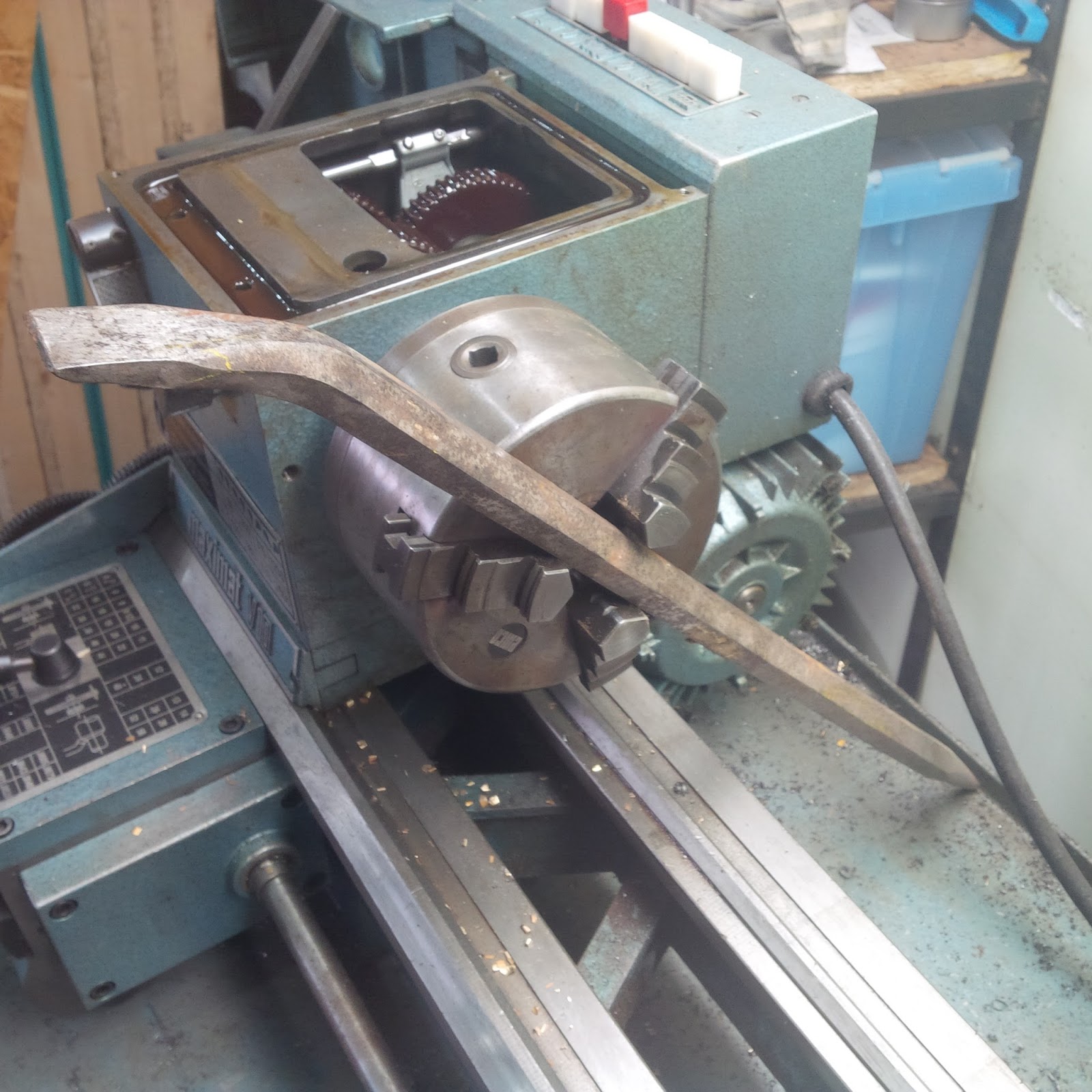
I decided to put the milling head in the 4-jaw chuck, face off the cracked rim, bore out the inside and thread it, then turn a piece of metal stub with an overhanging ridge at the front and a matching thread. Then use loctite to hold it all in place and that should be it.
I was really glad that I had already built the Back Plate for my 4-Jaw Chuck just a few days earlier so all I had to do is put some aluminum flashing between the part and the jaws of the chuck, dial it in and go to it.
The job ended up taking about 10 hours but most of that was because I'm still learning and everything takes a lot longer. It was actually quite a fun project and what I found most exciting is that a catastrophic failure like that would have meant the end of the tool (replacements are in the hundreds of dollars) and now I was able to fix it all for free.
Videos:
Pictures:
Milling the dividing head sector arm at an angle
Another view of what I was doing when the head broke off
The milling head where it landed. Luckily it didn't break anything or hurt anyone
Close-up of the cracked cast
The broken off ring still in the milling head
Another view of the broken off ring
The ring where it was before it broke off
Close-up of the broken milling head. The only place it was still attached (for who knows how long) is in the red oval
The milling head support resting on the lathe
Dimensions of the milling head support
After I faced off the cracked cast and got ready to bore out the inside to 2"
The inside bored out to 2"
I decided to use an 11 TPI internal thread
After the thread was cut
Another view of the cleaned up and threaded milling head support
Getting ready to turn down a 4" chunk of 10V45 (I didn't have any 2-3/4" stock) to 2.675"
Almost there
Doing a scratch pass with 11 TPI male thread
The rough finished part
Locking it in place with permanent (red) loctite
Supporting the head with a dead center so as to give better accessibility and turning it down to final size
Another view from a bit further away
Another angle
Close-up of the rough turned lip
Using a parting tool to finish the part to size and make it 100% concentric
Close-up of the finished job
Another view
Cleaning out the 20-30 year old stuff that was stuck behind the milling head column support bracket
Milling head was made in 1971
Taking the milling head column and cleaning it all up with some sand paper
Another "Before" view of the milling head column
After it was all nice and shiny
Another view of the polished milling head column
All the parts cleaned and shined up
Another view
Close-up of the top of the cleaned milling head column
Process:
A few days ago when I picked up one of our dining room chairs I noticed that over the years of usage (small kids are pretty hard on furniture!) the screws holding down the sitting surface had become stripped and the sitting area was just loosely tied to the rest of the chair.
At first I was considering to cut the fabric out around the screw, drill a hole, glue in a piece of dowel and then drill a small hole, but I remembered that I had bought a pocket screw hole jig a few years ago and since the screws were not normally visible I decided to just drill a new pocket hole in the chair frame and screw down the sitting surface at its new location.
The whole thing took about half an hour and now my little kiddos will be a lot safer!
Pictures:
The chair with the sitting area removed
The place where the screw was stripped out
My pocket hole jig
The pocket hole jig attached to the chair frame
The new pocket hole drilled about 1.5" beside the old (stripped) one
Update:
I ended up re-doing the spindle lock with a more Permanent Solution a few months later (see link)
Project:
Creating a way to lock the spindle of my metal lathe so I can change chucks
Difficulty Level (Easy, Medium, Hard, Insane):
Medium
Process:
Now that I have created a Back Plate For My 4-Jaw Chuck I found that it was a bit tedious to change the chucks because my lathe doesn't have a way to lock the spindle and the chuck is screwed onto the spindle.
I found a way to do it by inserting a punch through two holes in the spindle and then using a pry bar on the chuck side and a pipe wrench on the other side, but it was a bet tedious because I'd have to pull out the lathe stand, open the side cover and then try to hold all the different tools in place so I figured it would be a good idea to create a more permanent and easier to use solution.
The solution actually ended up fairly simple: I had to turn two pieces of metal, one that mounts to the spindle with two set screws into the two existing holes and a second one with a handle that can be attached to that first part actually keeping the spindle from turning.
Videos:
Pictures:
Using a pry bar to lock the chuck in place
Using a punch and a pipe wrench to un-twist the chuck
Close-up of the punch and pipe wrench
Drilling the part that will mount to the spindle
Diagram of my measurements
Drilling with a 1" drill
Making sure the holes are aligned with those in the spindle
I had to use a rasp and grind off about 1/8" of the inside cover to allow me to easily open/close the cover
The outside view of where I had to grind off some aluminum
The adapter mounted on the spindle
After I cut some groves into the adapter
Using the set screws to tighten the adapter to the spindle
Another view
The adapter just barely sticking out of the side cover
The second part turned and welded to a 13.5" piece of metal
Another view
Close-up of the locked spindle
Another view
Cross-section of how I fastened the first part to the spindle
Difficulty Level (Easy, Medium, Hard, Insane):
Medium
Process:
When I got my metal lathe it unfortunately didn't come with a 4-jaw chuck which is fine for most jobs but any time a job requires an off-center or square piece of stock, a 4-jaw chuck makes life a lot easier.
I ended up buying a cheap-o chinese 4-jaw chuck at Busy Bee Tools but still had to mount it on my lathe. Luckily, I bought a bunch of metal blanks at one of the auctions I went to recently. However, since this was one of my earliest projects it took me forever to do and when I finally finished I realized that my digital calipers had unfortunately zeroed out at 4 thousands instead of 0 which meant that the final size of the alignment rim was 0.004" over sized.
I thought maybe I could make it work, but because it was the base for the chuck on which all other work would be turned I realized that it was not going to be accurate so unfortunately I had to start the project all over again.
The second attempt went a lot faster but it still took me about 5 hours to do and just when I was getting ready to do the final cut, being very careful the calipers were zeroed properly I mis-calculated my adjustment and bored the center alignment hole 20 frickin thousands over!!! I was so mad!
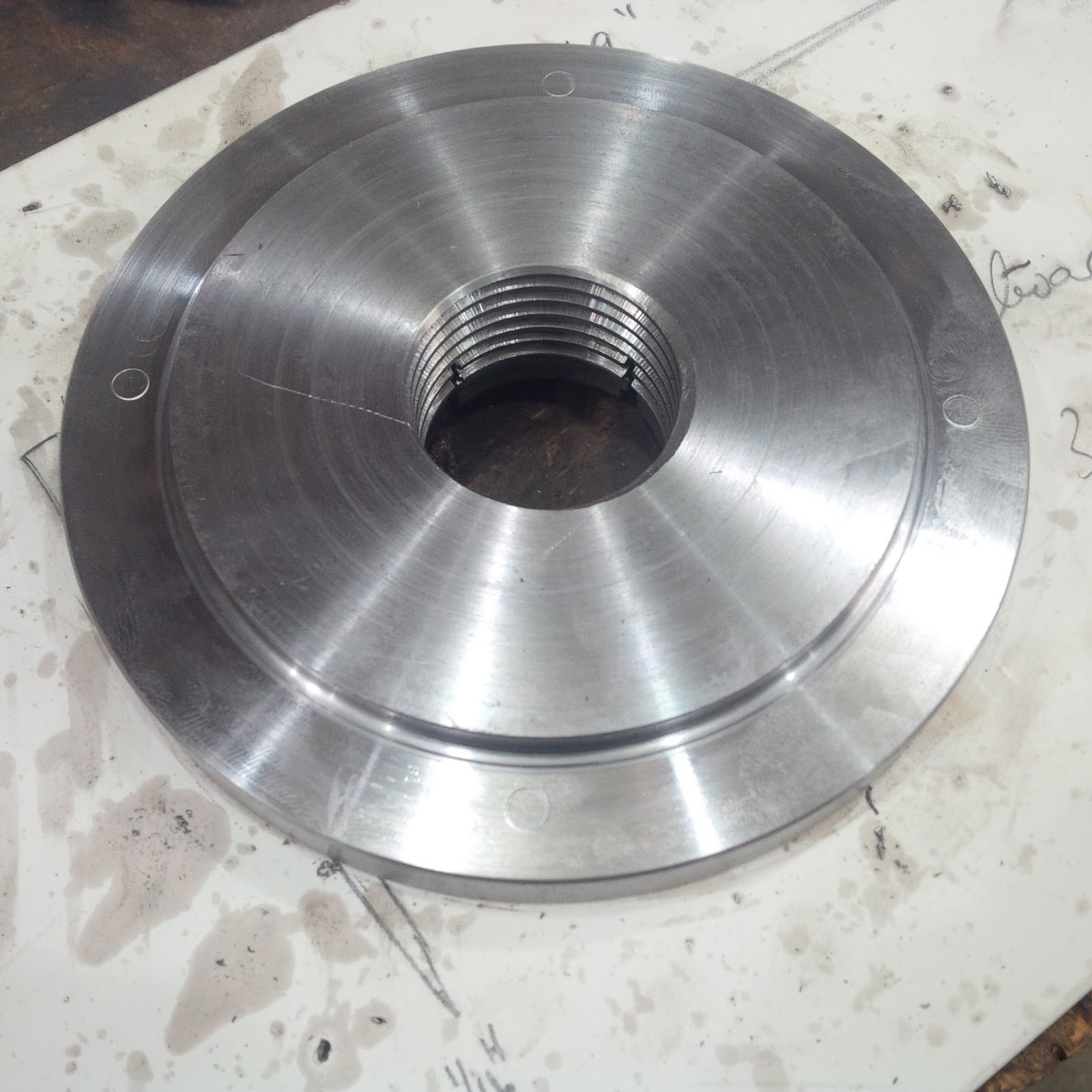
So I started the 3rd attempt. It went faster than the first two and probably cranked out the part in about 3 and a half hours and this time it was perfect! Normally I wouldn't be as picky when it comes to metal working but because any inaccuracies in the chuck back plate would be affecting all other work done with that chuck I wanted it to be perfect and after about 15 hours of machining I finally had me a proper 4-jaw chuck.
Videos:
Pictures:
The disc as I got it at the auction
Facing to size
Facing the second time
Ready for cutting the 8TPI 1.5" diameter inside thread
Another view before starting to cut the inside thread
The finished back plate (0.004" over sized)
Close-up of the internal 8TPI 1.5" thread
Close-up of the finish
Drilling the mounting holes for the chuck
And my 3rd try with the 0.004" over-sized back plate beside it
Turning down the hub 50 thou at a time
Getting ready to cut the grooves
The grooves cut and the tightening collar installed
Another view
Laying out the holes for mounting the chuck
The finished back plate (L) and the over-sized one (R)
The chuck mounted on the lathe
Another view
A close-up of the back plate
Tools:
Drill press
Metal lathe
Metal scribe
Digital calipers
Alan keys