Designing a brake for our zip line
Difficulty Level (Easy, Medium, Hard, Insane):
Medium
Process:
The zip line brake system has gone through several revisions over the last year or two, mainly:
- Simple tire at the end of the zip line
- Elastics tied to a wooden block
- Counter-weight system tied to a stopper block
I had originally used 1/4" steel wire for the zip line itself which would have been fine, but again, in an attempt to minimize all risk of the line ever snapping I upgraded it to a 3/8" wire which has a braking strength of over 12,000 lbs and a "safe load of about 2,500 lbs. Because of that upgrade I had about 100 feet of the 1/4" steel wire left over which I tied between our club house and the end of the zip line, tied a triple chord (braided) elastic rope to it and the other end to a wooden block which slid along the main wire. So every time a kid would go down, the zip line trolley would hit the wooden block, engage the elastic rope and slow the kids down over a distance of about 20 feet.
However, after a year of using the elastic rope very successfully, the sun and weather started breaking down the elastic so I had to come up with a more permanent solution. Such was the counter-weight zip line brake design born. I've seen these designs a lot in my university physics classes and I started thinking about how to implement this typical pulley system. Essentially, the potential energy of the zip line user at the start of the zip line is converted into kinetic energy and through the counter weight, as they hit the wooden stopper it raises the weight and converts the kids kinetic energy back into potential energy.
If the drop in height from the start of the zip line to the end is 6 feet and the kid weighs 50lbs I would have to attach a 50lbs bucket at the counter weight end and it will be raised about 6 feet as the zip line brake slows down the kid. In theory that sounds about right and the reason I used the pulley system is that instead of having a simple 6 foot stopping distance I can triple that to about 18 feet.
After casting the aluminum pulleys with my Home Foundry and my Propane Burner I put them on my Gingery Lathe, turned them down to size, welded a "cage" around the pulley, installed them on the zip line and hooked them up to a 3/16" steel wire using the "Flemish Eye" technique and some wire clamps.
One thing I noticed is that because the kids are all fairly light, my counter weight had to be equally light whose down-force wasn't quite strong enough to pull the wooden block back up the zip line to its starting point because the steel wire created too much friction against the wooden block so I knew I had to "eigenheer" something to fix that.
I had recently purchased some 1" teflon pieces at a local scrap yard so I cut up a piece about 10" long and 1" by 1" wide, put it in my lathe, turned it down to 7/8" diameter, drilled a 1/2" hole through it and cut the teflon sleeve in half with my band saw. All that was left to do is drill out the wooden block to 3/4", put the teflon sleeve halves around the 3/8" steel wire and hammer it into the wooden block. Now I had a low friction sleeve around the wire that made the wooden block slide back up the zip line with very minimal effort.
I had my son test it and after doing a few adjustments to the wire guides around the pulleys it was another project completed.
Pictures:
 |
| The patterns for the pulleys |
 |
| The pattern in the drag |
 |
| After the aluminum was poured |
 |
| After the cast was shaken out of the mold |
 |
| The pulleys before they were cleaned up |
 |
| After they were cleaned up on the table saw |
 |
| Turning them to size on the lathe |
 |
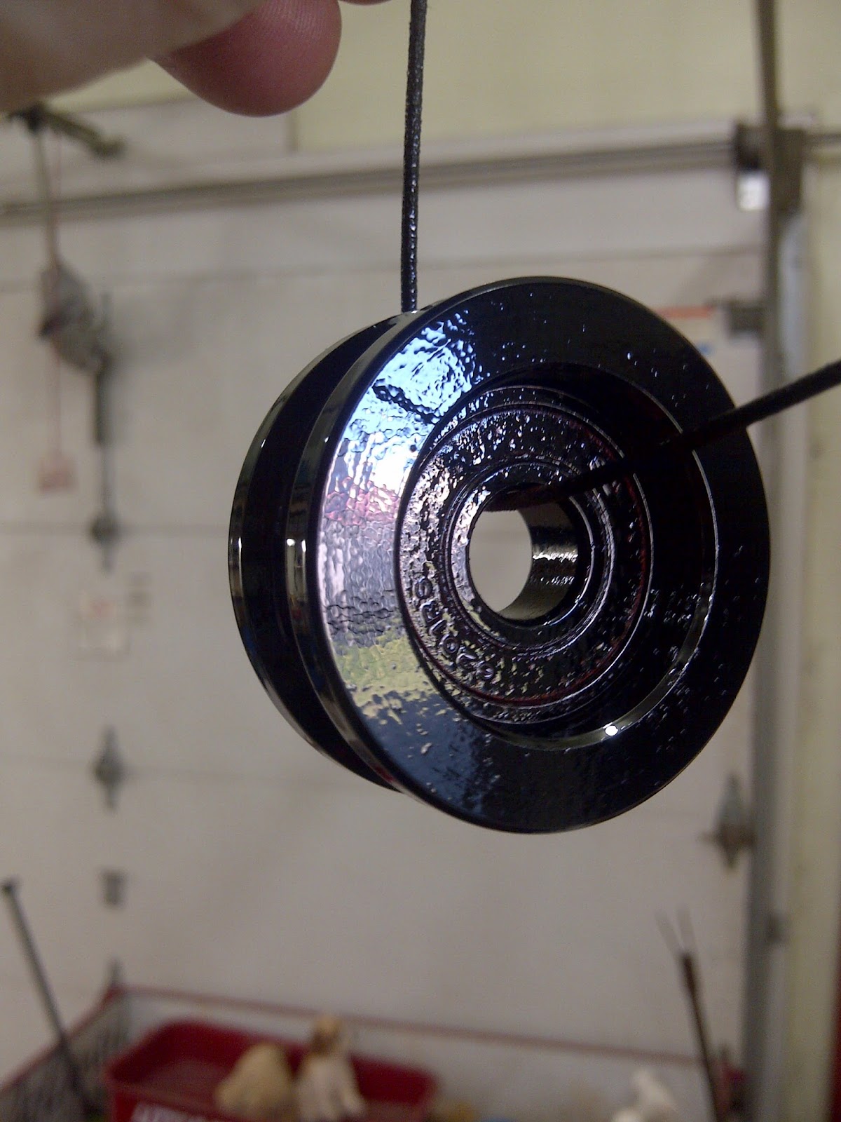
| One of the finished pulleys |
 |
| Welding the bracket to hold the counter weight pulley |
 |
| After the counter weight pulley was installed |
 |
| Cutting out the wire guards |
 |
| Welding the wire guards to the counter weight pulley holder |
 |
| Testing it out with a rope |
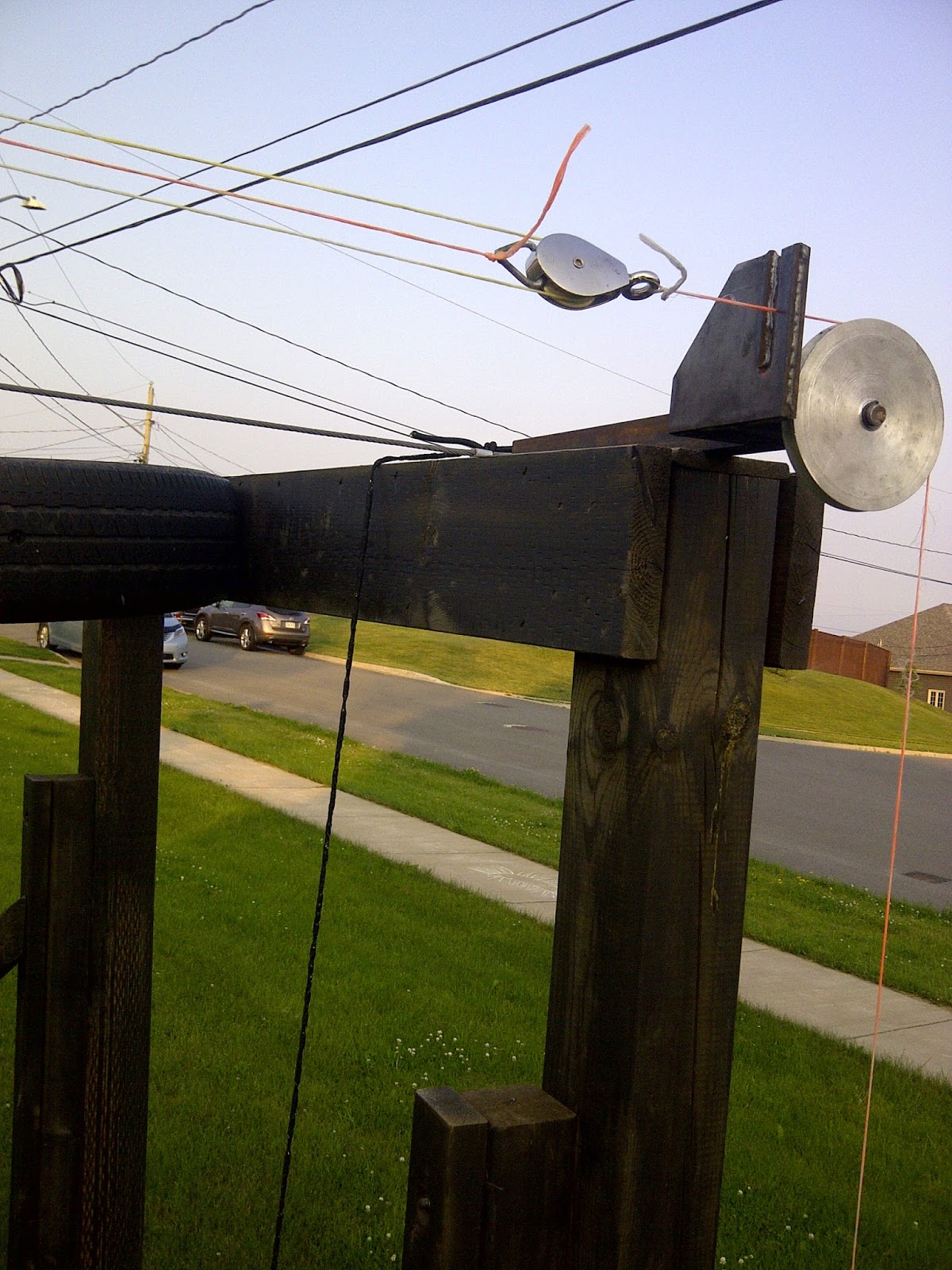 |
| Seems to work |
 |
| Nathaniel after he just tried the zip line brake |
 |
| The turned, drilled and split Teflon sleeve for the wooden block |
 |
| After the two Teflon halves were put together |
 |
| The drilled out wooden stop block |
 |
| Test install of the Teflon sleeve |
 |
| Another view of the test-installed Teflon sleeve |
 |
| Getting ready to install the Teflon sleeve |
 |
| The installed Teflon sleeve in the wooden stop block |
 |
| The dual pulley |
 |
| A close up of the wire guards |
 |
| Another view of the installed wire guards from below this time |
Tools:
Home Foundry
Propane Burner
Gingery Lathe
Measuring tape
Pencil
Angle grinder
MIG welder
Table saw
Snap ring pliers
Adjustable wrench
Clamps
Drill
Drill press
Ladder
Screwdriver
Tap & die set
Materials:
About 2 lbs of aluminum
Scrap metal
100' of 3/16" aircraft cable
Six 1/2" Snap rings
Quick link chain links
12"elastic rope
Cost:
$50.00
Time:
15 hrs
Savings:
$300
Conclusion:
It works awesome. I just wish it wasn't winter soon...